Greetings to engineers, designers, and infrastructure enthusiasts! Delve into the technical intricacies of Civil 3D corridors with our comprehensive cheat sheet. Covering alignments, profiles, assemblies, corridors, sections, and volumetric calculations, this resource is your go-to guide. Whether you’re new to these concepts or a seasoned pro, unlock advanced techniques and elevate your corridor design expertise. Start your journey to corridor mastery today!
To create a corridor, you must have an alignment (baseline), a profile (existing or proposed), and an assembly. You can also use a feature line for the alignment and profile pairing.
Alignments
You have 2 choices in defining an alignment from scratch:
Home tab > Create Design > Alignment > Alignment Creation ToolsHome Tab > Create Design > Alignment > Create Alignment from Objects.
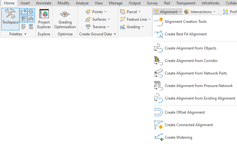
Alignment Creation Tools gives you the constrained based design options. Constrained based design will maintain tangency based on 3 choices:
- Fixed curve – These commands are like an AutoCAD arc but have a third point along the arc.

- Floating Curve – Maintain tangency at the start, while one end is not connected to another object. For example, curves off the end of a line.

- Free Curve – These entity types are very similar to the AutoCAD “fillet” command, but give you added control.

Fixed, free, and floating lines are also available (shown below). Many methods for producing spirals are available, but just not shown in this document.

Listing and Labeling off an Alignment
Inquiry Tool
“Analyze” ribbon tab > Inquiry Tool– Once in the inquiry tool, there are 4 pre-defined listing commands to obtain information from an alignment.

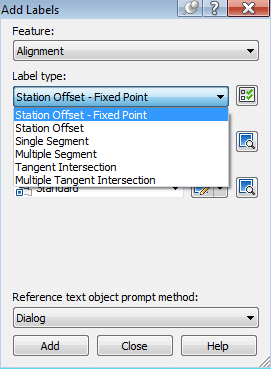
Add Alignment Labels
“Annotate” ribbon tab > Add Labels > Alignment > Add Alignment Labels– This command may add labels to offset stations as well as alignment segments.
Existing/Proposed Profiles and Profile Views
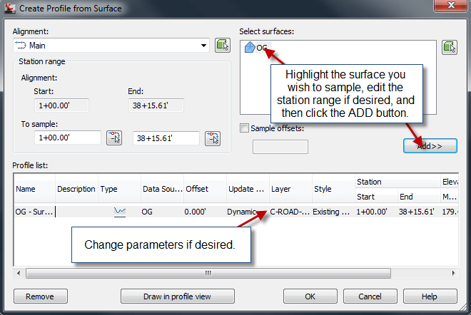
Create Surface Profile
“Home” ribbon tab > Profile > Create Surface Profile
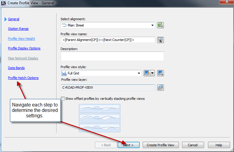
Create Profile View
“Home” ribbon tab > Profile View > Create Profile View
Profile Creation Tools
“Home” ribbon tab > Profile > Profile Creation Tools

Profile View Properties
Profile View Properties, “Bands” tab, Set “Profile 2” to the design profile. (If you use a band style with FG and EG elevations.)
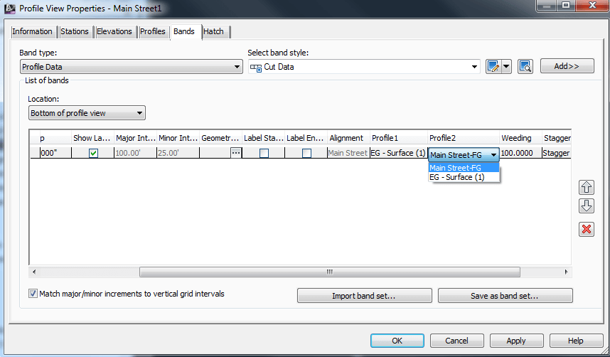
Listing and Labeling Profiles and Profile Views
Inquiry Tool
“Analyze” ribbon tab > Inquiry Tool – There are several listing commands for profiles and profile views.
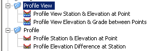
Add Profile View Labels
“Annotate” ribbon tab > All Labels > Profile View > Add Profile View Labels
Create/Edit Assemblies
Create Assembly
“Home” ribbon tab > Assembly > Create Assembly – Choose the appropriate styles and place the baseline somewhere in the drawing.
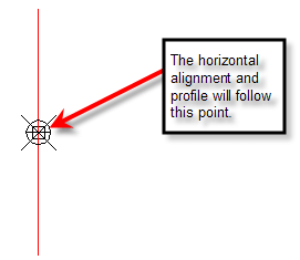
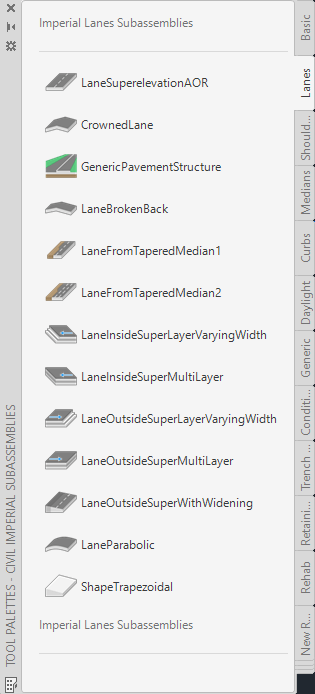
Tool Palettes
Home tab > Palettes > Tool Palettes – This displays the tool palettes that contain pre-defined sub-assemblies to be placed on the assembly.
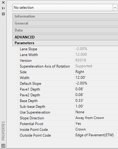
- Find the desired subassembly, left click the tool, fill out the properties, and then choose the attachment point on the assembly. You can also attach the subassembly and edit the parameters later as well.
- Rename the subassembly to an appropriate name. This will be important later in the definition of the corridor.
Create/Edit Corridors
Create Corridor
“Home” ribbon tab > Create Design > Corridor
- Choose the horizontal alignment (baseline), then the profile, the assembly, and the target surface in the dialog box (not shown here). Corridor Properties dialog shown below
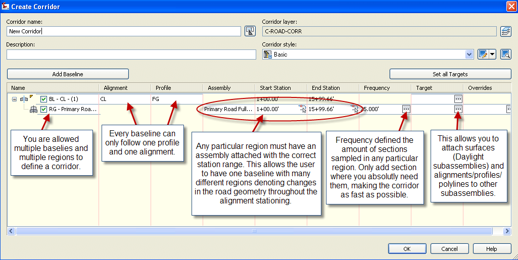
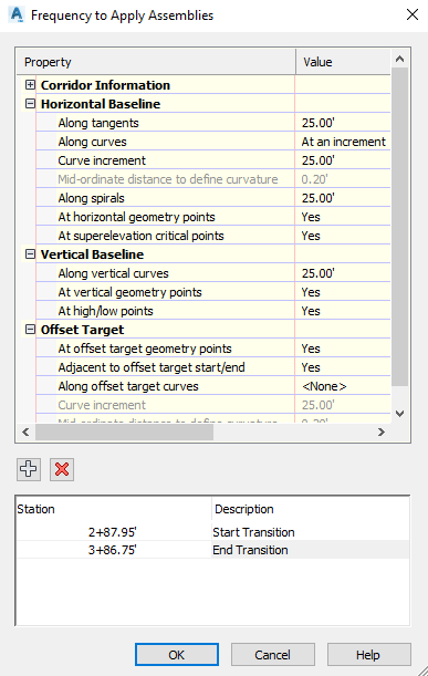

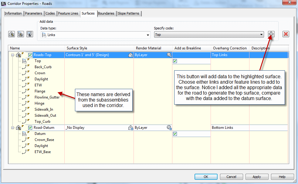
Create Corridor Surfaces (Within Corridor Properties)
Surfaces can be used to create the finished surface as well as calculate volumes. Typically, the top surface will become the finished ground surface while the datum surface will become the volume calculation surface. See the manual for further details.
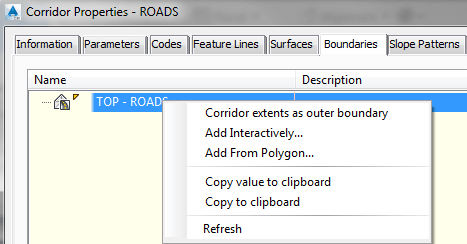
Add a Boundary to the Corridor Surface
Sections
Sections are used for 2 things: (1) Plotting sections at desired stations, and (2) Calculating the volumes from a corridor. To accomplish the later, you must have added a corridor surface to represent the datum surface before sampling the sections.
Sample Lines
“Home” ribbon tab > Sample Lines
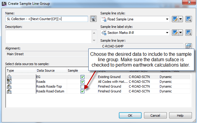
Next to appear is the “Sample Line Tools” dialog box. See below for further explanation.

Calculate Volumes
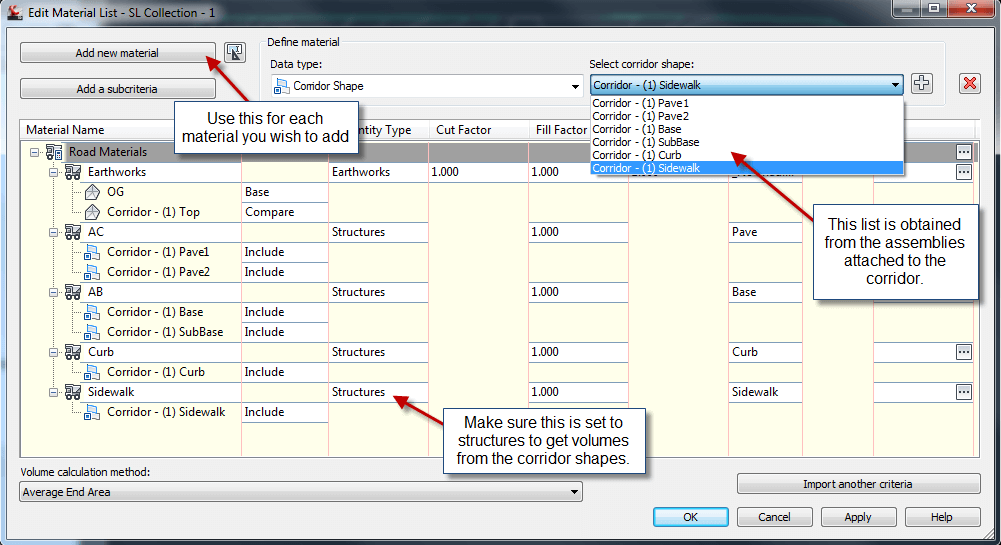
There are two (2) types of volumes you can extract from a corridor: (1) cut and fill; (2) quantity of material.
Cut and Fill
After creating the datum surface in corridor properties, you can simply use the volumes dashboard to see the volumes. This is further explained in the Grading cheat sheet.
“Analyze” ribbon tab > Volumes Dashboard
Calculating volumes based on station ranges. (Cut and Fill)
Compute Materials
“Analyze” ribbon tab > Compute Materials
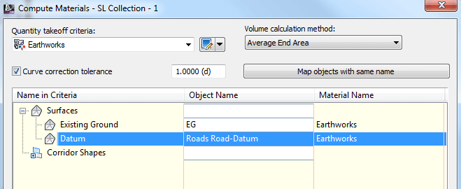
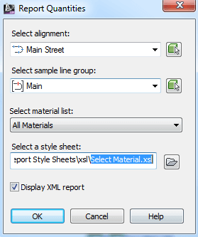
Volume Report
“Analyze” ribbon tab > Volume Report
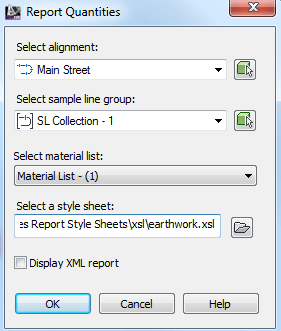
Calculating volumes based on station ranges. (Quantity of Material)
Compute Materials
“Analyze” ribbon tab > Compute Materials
Volume Report
“Analyze” ribbon tab > Volume Report


0 Nhận xét